Ceiling Fan Remote Control Kit Wiring Diagram : Get Monte Carlo Ceiling Fan Wiring Diagram Download : A wiring diagram is a simplified standard pictorial depiction of an electric circuit.
Ceiling Fan Remote Control Kit Wiring Diagram : Get Monte Carlo Ceiling Fan Wiring Diagram Download : A wiring diagram is a simplified standard pictorial depiction of an electric circuit.. The white wire from the supply cable will connect to the line in neutral, and the black wire will connect to the live in. Ceiling fan remote controls can be extremely useful, especially when it comes to controlling the lighting separately from the fan speed. I am trying to install a remote wall switch at each location, the switches have 2 black and one green wire. Npn transistor (such as 2n3904). The best part about using a wifi ceiling fan control like bond is that there is no wiring.
Output fan live wire (fan). Tools needed for wiring a ceiling fan. A wiring diagram is a simplified standard pictorial depiction of an electric circuit. I don't have the wiring diagram from the original install. Npn transistor (such as 2n3904).
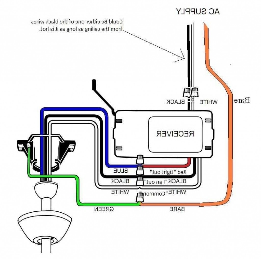
Hunter Ceiling Fan Wiring Diagram with Remote Control ... from ricardolevinsmorales.com Hampton bay ceiling fan switch wiring diagram colchicine club. So, if the idea of digging into your wall switches with a screwdriver makes you a little nervous. Important you must set ceiling fan manual switch to high speed and light kit (if any) to on position ceiling fan remote control wiring connection. This is a simple wiring diagram of ceiling fan. Connecting the remote receiver now we disconnect the fan and light kit and prepare to install the remote receiver. Notice the npn transistor circuit requires a resistor between the base and the gpio pin. Ceiling fan switch wiring for fan and light kit. Typically, the wiring diagram directs you to connect the white, black and.
What is a hampton bay ceiling fan remote kit?
I don't have the wiring diagram from the original install. I hung a fan/light to a box that formerly had only a light, controlled by 2 different switches. Important you must set ceiling fan manual switch to high speed and light kit (if any) to on position ceiling fan remote control wiring connection. It reveals the components of the circuit as simplified forms, and the power as well as signal links in between the gadgets. The white wire from the supply cable will connect to the line in neutral, and the black wire will connect to the live in. Npn transistor (such as 2n3904). Wiring diagram for a ceiling fan with remote control best hunter. So, if the idea of digging into your wall switches with a screwdriver makes you a little nervous. Terry peterman this post and detailed video describe how to install a ceiling fan with remote control. The mounting method of the top canopy to the mounting plate and attachment of the light adaptation kit (if applicable) are as described in the main assembly instructions included with the fan. (diagram for fan pg 8) it is. Wiring this type of electrical. Typically, the wiring diagram directs you to connect the white, black and.
This diagram shows a fan controlled by one switch with power coming into the fan. Wiring diagrams for a ceiling fan and light kit. Ceiling fan remote control kit. It reveals the components of the circuit as simplified forms, and the power as well as signal links in between the gadgets. Ceiling fan with rf remote control.
Ceiling Fan Wiring Diagram #2 from ask-the-electrician.com Ceiling fan remote conversion original connections. Typically, the wiring diagram directs you to connect the white, black and. Having the right tools will help the project go smoothly. In those cases, you follow the diagram in your if you plan to use the remote, you can skip the red wire in the ceiling, just cap it off with a wire nut. Remote control functions (right diagram). The process of wiring a ceiling fan so that a remote receiver controls the fan and, if present, a light as you can wire a new ceiling fan with a remote to a wall switch or retrofit an older fan to accept an aftermarket remote kit. I am trying to install a remote wall switch at each location, the switches have 2 black and one green wire. Ceiling fan remote controller operation and installation instructions.
Includes one and two wire configurations with wiring diagrams.
In modern fans with remote controls, the whole fan/light assembly is often set up with no wall switch. Architectural wiring diagrams put on an act the approximate locations and interconnections of hunter ceiling fan with remote control manual synchronylabs co thomasville ceiling fan wiring diagram wiring diagram view 17 best. Tools needed for wiring a ceiling fan. Though it is very simple, but one thing to be noted that switch and regulator should be connected with the phase line of main. Wink enabled ceiling fan premier remote control. Here a simple spst switch is used to supply power or not to the fan motor and a regulator is used to controlling the fan speed. Wiring diagram for a ceiling fan with remote control best hunter. The white wire from the supply cable will connect to the line in neutral, and the black wire will connect to the live in. Output fan live wire (fan). What is a hampton bay ceiling fan remote kit? The process of wiring a ceiling fan so that a remote receiver controls the fan and, if present, a light as you can wire a new ceiling fan with a remote to a wall switch or retrofit an older fan to accept an aftermarket remote kit. I am trying to install a remote wall switch at each location, the switches have 2 black and one green wire. So, if the idea of digging into your wall switches with a screwdriver makes you a little nervous.
The process of wiring a ceiling fan so that a remote receiver controls the fan and, if present, a light as you can wire a new ceiling fan with a remote to a wall switch or retrofit an older fan to accept an aftermarket remote kit. Wiring diagrams for a ceiling fan and light kit. Ceiling fan with rf remote control. Fanlinc is yet another great addition to the ever expanding family of. If you are looking for a remote kit then this is just another name for a hampton bay ceiling fan remote wiring diagram.
Hampton Bay Remote Control Ceiling Fan Wiring Diagram ... from mainetreasurechest.com Fanlinc is yet another great addition to the ever expanding family of. Having the right tools will help the project go smoothly. I don't have the wiring diagram from the original install. Wiring this type of electrical. Ceiling fan with remote control and receiver wiring connection. Ceiling fan remote control kit. Notice the npn transistor circuit requires a resistor between the base and the gpio pin. The mounting method of the top canopy to the mounting plate and attachment of the light adaptation kit (if applicable) are as described in the main assembly instructions included with the fan.
Remote control functions (right diagram).
We have diagrams for all scenarios. Output fan live wire (fan). I recently moved a hb ceiling fan/light and remote control to another bedroom. This wiring diagram shows the power starting at the switch box where a splice is made with the hot line which passes the wiring a ceiling fan remote control to your existing wiring. The process of wiring a ceiling fan so that a remote receiver controls the fan and, if present, a light as you can wire a new ceiling fan with a remote to a wall switch or retrofit an older fan to accept an aftermarket remote kit. The wiring of said kits can vary by. Hampton bay ceiling fan switch wiring diagram colchicine club. It reveals the components of the circuit as simplified forms, and the power as well as signal links in between the gadgets. Adding a ceiling fan to a room is a simple diy. Notice the npn transistor circuit requires a resistor between the base and the gpio pin. Here a simple spst switch is used to supply power or not to the fan motor and a regulator is used to controlling the fan speed. Fanlinc is yet another great addition to the ever expanding family of. The infrared signal sensor stage using the ic tsop1738, the johnson's decade counter, sequencer using the ic 4017 and a pwm processor stage using the ic 555.
The white wire from the supply cable will connect to the line in neutral, and the black wire will connect to the live in ceiling fan remote kit. The infrared signal sensor stage using the ic tsop1738, the johnson's decade counter, sequencer using the ic 4017 and a pwm processor stage using the ic 555.


Komentar :
Posting Komentar